Thursday, August 31, 2023

Data Integration Strategies

 1. Data Consolidation: refers to combining data from various sources into a centralized data store that acts as a single source of truth for the organization. Enabling you to store data in a unified store, it can be used for all your reporting and analytics use cases and can serve as a data source for other applications.  However, there is some data latency in this data integration method. There will be some time difference between when the data is updated in the original data source and when it gets updated in your central repository.


2. Data Federation: Unlike the data consolidation strategy, where you move all data to a single source of truth, data federation offers a virtual database. Simplifying access for consuming users and front-end applications, this data integration technique performs data abstraction to create a uniform user interface for easy data access and retrieval. Your queries to the federated virtual database are sent to the relevant data source, which then returns the data you requested. This is an on-demand data solution compared to other real-time data integration techniques.


3. Data propagation: uses applications for data transfer from enterprise data warehouses to multiple source data marts on an event driven-basis. As data continues to be updated in the warehouse, the respective data marts are updated synchronously or asynchronously. 


4. Middleware Data Integration: uses a middleware application to transfer data from multiple applications and source systems into a central repository. This approach validates and formats the data before beginning the transfer to the data store, thereby significantly reducing the chances of compromised data integrity or disorganized data. This is especially beneficial for integrating older systems with newer ones, as the middleware can help transform the legacy data into a format that the newer systems can understand.


5. Common storage integration (also called Data Warehousing): Generally referred to as Common Data Storage, data is replicated from the source to a data warehouse. this data integration strategy includes cleansing, formatting, and transforming data before storing it in the data warehouse.


Data integration techniques

1) Change Data Capture (CDC)

What is it? Change Data Capture (CDC) is a data replication technique that makes a copy of the source data into your data storage. 


Pros
:

Faster data replication. CDC is optimized for streamlining data replication. It only moves the data that has been altered (added, deleted, updated) since the last data integration. Hence saving you networking costs during data movement and speeding up the overall data replication process.
Event-driven. CDC can be configured to fire at every source data change event. Making it a great ally for keeping data consistent between your source systems and data storage.

Cons:
Limited to SQL sources. CDC is primarily designed to replicate data from SQL databases and data warehouses. It’s hard to generalize it to other data sources.

No data transformation. CDC does one thing (data replication) and it does that one thing well. But it cannot be used to sanitize and cleanse data, or to provide more complex data transformation (e.g., prepare data for data analysis). 

Best practice:
This data integration method is especially suited for big data sources, where the size of the data is a limiting factor for your integration operations.  CDC analyzes the binary log to determine events that changed the data since the last replication and extracts the new rows during replication for a lightweight, fast, and zero-maintenance data replication.


2) ETL

What is it?
ETL is a data integration approach that develops specific and advanced techniques for each stage of this data integration process (extract, transform, load).


Pros:

Customizable data extractors. ETL is not limited to any data source. From applications to SQL databases, ETL can integrate data from (theoretically) any source. Customizable data transformations. ETL tools are the most common leaders in the data transformation space. Offering solutions for advanced data transformations (aggregations, complex SQL or Python queries, machine learning filters, etc.), that are not often present in simple data integration platforms.  Customizable data storage. Unlike common integration storage (data warehousing), ETL tools can integrate data into one or more different data storages: from data lakes for unstructured data to BI tools directly for reverse ETL.

Cons:
No data consolidation guarantee. Because ETL tools offer more customizability - the freedom to specify the source, transformations, and destinations yourself - there is no predefined data model or unified data view. To guarantee data quality, you’ll have to impose data management and governance rules alongside this technique. 

Greater integration latency. Unlike CDC or middleware data integration, ETL paradigms suffer from the same latency as common data integration storage. The data transformation layer introduces latencies that make them poor candidates for real-time data integration. 

Best practice: ETL tools often offer all the functionalities of common integration storage. Pick this integration paradigm if you envision your data model changing and adapting to your business needs. It is easier to adapt ETL integrations to a data warehouse than the other way around. For example,  ETL is designed with plug-and-play components, that can easily be swapped and customized, empowering you to pick the best-performing architecture for your data integration needs. 

Wednesday, July 5, 2023

Software Estimation Techniques [Use-Case Points]

 Estimation determines how much money, effort, resources, and time it will take to build a specific system or product. 

Project scope must be understood before the estimation process begins. 

A Use-Case is a series of related interactions between a user and a system that enables the user to achieve a goal.

Use-Cases are a way to capture functional requirements of a system. The user of the system is referred to as an ‘Actor’. Use-Cases are fundamentally in text form.

The Use Case Points (UCP) method can be used to estimate software development effort based on a use-case model and two sets of adjustment factors relating to the environmental and technical complexity of a project. The question arises whether all of these components are important from the effort estimation point of view.


The Use-Case Points counting process has the following steps:

1) Calculate unadjusted UCPs

1.1) Determine Unadjusted Use-Case Weight

1.2) Determine Unadjusted Actor Weight

1.3) Calculate Unadjusted Use-Case Points

2) Adjust for technical complexity

3) Adjust for environmental complexity

4) Calculate adjusted UCPs


1.1) How to determine Unadjusted Use-Case Weight?

Transaction is equivalent to a step in the Use-Case. Find the number of transactions by counting the steps in the Use-Case.

Classify each Use-Case as Simple, Average or Complex based on the number of transactions in the Use-Case. Also, assign Use-Case Weight as shown in the following table:


Karner originally proposed ignoring transactions in the extensions part of a use case. However, this was probably largely because extensions were not as commonly used in the use cases he worked with during the era when he first proposed use case points (1993). 

Extensions clearly represent a significant amount of work and need to be included in any reasonable estimating effort.

So, from previous figure, we can say that we have 10 transactions.

but, Counting the number of transactions in a use case with extensions requires a small amount of caution. That is, you cannot simply count the number of lines in the extension part of the template and add those to the lines in the main success scenario.

So, we can consider step 2a1, 2b1, and 2c1 is just a notification as a result of step 2 and count them all as one transaction. So, we just have 8 transactions. and because any use case has more than 7 steps consider as complex, we will give it 15 point.

Repeat this process for each use case in the project. The sum of the weights for each use case is known as the Unadjusted Use Case Weight, or UUCW. next table shows how to calculate UUCW for a project with 40 simple use cases, 21 average, and 10 complex


1.2) How to determine Unadjusted Actor Weight?

The transactions (or steps) of a use case are one aspect of the complexity of a use case, the actors involved in a use case are another. An actor in a use case might be a person, another program, a piece of hardware, and so on. Some actors, such as a user working with a straightforward command-line interface, have very simple needs and increase the complexity of a use case only slightly. Other actors, such as a user working with a highly interactive graphical user interface, have a much more significant impact on the effort to develop a use case. To capture these differences, each actor in the system is classified as simple, average, or complex, and is assigned a weight in the same way the use cases were weighted.

In Karner’s use case point system, a simple actor is another system that is interacted with through an API (Application Programming Interface). An average actor may be either a person interacting through a text-based user interface or another system interacting through a protocol such as TCP/IP, HTTP, or SOAP. A complex actor is a human interacting with the system though a graphical user interface GUI. This is summarized, and the weight of each actor type is given, in Table 3.


Each actor in the proposed system is assessed as either simple, average, or complex and is weighted accordingly. The sum of all actor weights in known as Unadjusted Actor Weight (UAW). This is shown for a sample project in Table 4.


1.3) How to calculate Unadjusted Use-Case Points?

Combining the Unadjusted Use Case Weight (UUCW) and the Unadjusted Actor Weight (UAW) gives the unadjusted size of the overall system. This is referred to as Unadjusted Use Case Points (UUCP).

Unadjusted Use-Case Points (UUCP) = UUCW + UAW

Using our example, UUCP is calculated as:

UUCP= 560 + 40 = 600


2) How to adjust for technical complexity?

Consider the 13 Factors that contribute to the impact of the Technical Complexity of a project on Use-Case Points and their corresponding Weights as given in the following table
Notes:
1) Distributed System: higher number means complex architect.
2) Response time/performance: higher number means increase importance for response time.
3) End user efficiency: higher number means project is critical to the end-user to complete his work.
4) Complex internal processing: zero means simple sql query, higher means complex calculations.
5) Code must be reusable: higher number means higher level of planning will be required.
6) Easy to install: higher number means more easy is required.
7) Easy to use: higher number means more usability required.
8) Portable: more supported platforms/OS, more rate required.
9) Easy to change: more changes expected more rating.
10) Concurrent: more Concurrent users means more rating.
11) special security: more custom security, (row level, column level , role level), means more rating.
12) direct access for third parties: more access means more rating.
13) Special user training facilities: the longer time for training required the more rating.

For each of the 13 Factors, you need to rate from 0 (irrelevant) to 5 (very important).

Technical Complexity Factor (TCF) = 0.6 + (0.01 * TFactor) 


3) How to adjust for environmental complexity?

Consider the 8 Environmental Factors that could affect the project execution and their corresponding Weights as given in the following table


Notes:
1) Familiar with the project, higher number means higher level of experience.
2) Application experience, for new application, rate will be 0, for update existing system, rate will be 5
3) Object-oriented experience: higher number means higher OO experience.
4) Lead analyst capability: higher number means good analysis.
5) Motivation: higher number means higher motivation. 
6) Stable requirements: higher number means less changes expected.
7) Part-time staff: higher number means most of stuff are part time.
8) Difficult programming language: higher number means harder lang to our stuff.

Environmental Factor (EF) = 1.4 + (-0.03 × EFactor)


5) How to calculate final Use Case Point (UCP )?

UCP = UUCP × TCF × EF

.


6) How to convert UCP to Man hours?

Karner originally proposed a ratio of 20 hours per use case point.

Schneider and Winters (1998) proposed a different approach, we need to calculate n1, and n2 first

  • n1= count of environment factor below 3 for items F1-F6
  • n2= count of environment factor above 3 for items F7-F8

  • if n1+n2 <=2   ====================> need 10-20 Man hrs per UCP
  • else if   n1+n2 between 3,4   ==========> need 14-28 Man hrs per UCP
  • else if   n1+n2 >4   =================> need 18-36 Man hrs per UCP
Consider that developer work 30 hours per weeks, 6 hours per day, 75% utilization.

The rest of their time will be sucked up by corporate overhead—answering email, attending meetings, and so on.


Summary


Notes: A better approach will often be to break the use case into a set of user stories and estimate the user stories in either story points or ideal time (Cohn 2005).


Reference

Estimating With Use Case Points by Mike Cohn, mike@mountaingoatsoftware.com

https://www.cs.cmu.edu/~jhm/DMS%202011/Presentations/Cohn%20-%20Estimating%20with%20Use%20Case%20Points_v2.pdf


https://www.youtube.com/watch?v=cAfWvYSQIHA


https://www.tutorialspoint.com/estimation_techniques/estimation_techniques_use_case_points.htm#


Sizing Sheet

Web
http://groups.umd.umich.edu/cis/tinytools/cis375/f17/team9-use-case-pts/Use_Case_Point_Calculator/

Excel
https://www.researchgate.net/file.PostFileLoader.html?id=550b927bef97130f038b4660&assetKey=AS%3A273739168583683%401442275911540

Thursday, May 18, 2023

Software Architecture Design Pattern

 The architecture of a software system is the shape given to that system by those who build it. The form of that shape is in the division of that system into components, the arrangement of those components, and the ways in which those components communicate with each other.

The purpose of that shape is to facilitate the development, deployment, operation, and maintenance of the software system contained within it.

Good architecture makes the system easy to understand, easy to develop, easy to maintain, and easy to deploy. The ultimate goal is to minimize the lifetime cost of the system and to maximize programmer productivity.


A good architecture must support:

  • The use cases and operation of the system:  architecture must support required throughput and response time for each use case that demands it.
  • The maintenance of the system: makes the system easy to change.
  • The development of the system: partitioning the system into well-isolated, independently developable components that can be allocated to teams that can work independently of each other.
  • The deployment of the system: A good architecture does not rely on dozens of little configuration scripts and property file tweaks. It does not require manual creation of directories or files that must be arranged just so. A good architecture helps the system to be immediately deployable after build.


Model-view-controller pattern

The model-view-controller (MVC) pattern divides an application into three components: A model, a view, and a controller.

The model, which is the central component of the pattern, contains the application data and core functionality. It is the dynamic data structure of the software application, and it controls the data and logic of the application. However, it does not contain the logic that describes how the data is presented to a user.

The view displays application data and interacts with the user. It can access data in the model but cannot understand the data, nor does it understand how the data can be manipulated.

The controller handles the input from the user and mediates between the model and the view. It listens to external inputs from the view or from a user and creates appropriate outputs. The controller interacts with the model by calling a method on it to generate appropriate responses.


Microservices pattern

Microservice is the process of implementing Service-oriented Architecture (SOA) by dividing the entire application as a collection of interconnected services, where each service will serve only one business need.
The microservices pattern involves creating multiple applications—or microservices—that can work interdependently, each service is self-contained and implements a single business capability. Although each microservice can be developed and deployed independently, its functionality is interwoven with other microservices.

Microservice Rules :

  • Independent: Each microservice should be independently deployable.
  • Coupling: All microservices should be loosely coupled with one another such that changes in one will not affect the other.
  • Business Goal: Each service unit of the entire application should be the smallest and capable of delivering one specific business goal.

The principles used to design Microservices are as follows:

  1. Independent & Autonomous Services
  2. Scalability
  3. Decentralization
  4. Resilient Services
  5. Real-Time Load Balancing
  6. Availability
  7. Continuous delivery through DevOps Integration
  8. Seamless API Integration and Continuous Monitoring
  9. Isolation from Failures
  10. Auto -Provisioning

Microservices Design Patterns are grouped into five major categories.
  • Decomposition Design Patterns: provides insight on how to decomposed application in smaller microservices.
  • Integration Design Patterns: handles the application behavior, how to get result of multiple services result in single call etc.
  • Database Design Patterns: how to define database, should have a separate database per service or use a shared database.
  • Observability Design Patterns: considers tracking of logging, performance metrices and so.
  • Cross Cutting Concern Design Patterns: deals with service discovery, external configurations, deployment scenarios etc.


Decomposition Design Patterns:

  1. Business Capability: split by business activity targeted to generate value. For example, in an e-commerce platform, we can split system by Sales and Customer service. Business capabilities may overlap, resulting in redundant services, like develop payment on Sales and on Customer Service!
  2. Domain-Driven Design(DDD): DDD refers to business as a domain, For example, in an e-commerce platform, we can split system by Ordering, Shipping, Payment.


Design Patterns of Microservices

  1. Aggregator
  2. API Gateway
  3. Chained or Chain of Responsibility
  4. Asynchronous Messaging
  5. Database or Shared Data
  6. Event Sourcing
  7. Branch
  8. Command Query Responsibility Segregator
  9. Circuit Breaker
  10. Decomposition


1) Aggregator Pattern

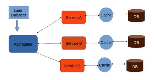
a simple web module will call different services as per requirements, the "Aggregator" is responsible for calling different services one by one. If we need to apply any business logic over the results of the service A, B and C, then we can implement the business logic in the aggregator itself.


1.1) Proxy Pattern (sort of aggregator)

Build one level of extra security by providing a dump proxy layer. This layer acts similar to the interface.


1.2) Chained Pattern

 Produces a single output which is a combination of multiple chained outputs, All the services will be chained up in a such a manner that the output of one service will be the input of the next service.
All these services use synchronous method. Also, until the request passes through all the services and the respective responses are generated, the client doesn’t get any output. So, it is always recommended to not to make a long chain, as the client will wait until the chain is completed


1.3) Branch Microservice Pattern

Allows the developer to configure service calls dynamically. All service calls will happen in a concurrent manner, which means service A can call Service B and C simultaneously, client can directly communicate with the service. 


1.4) Shared Resource Pattern

the client or the load balancer will directly communicate with each service whenever necessary. This is the most effective designing pattern followed widely in most organizations.


2) API Gateway Design Pattern

  • Acts as the entry point for all the microservices and can convert the protocol request from one type to other. 
  • Can also offload the authentication/authorization responsibility of the microservice.
  • Can also be considered as the proxy service to route a request to the concerned microservice. 
  • Can send the request to multiple services and similarly aggregate the results back to the composite or the consumer service. 


3) Asynchronous Message-Based Communication Design Pattern

If you have multiple microservices are required to interact each other and if you want to interact them without any dependency or make loosely coupled, than we should use Asynchronous message-based communication in Microservices Architecture. Because Asynchronous message-based communication is providing works with events. So events can place the communication between microservices, which called "event-driven communication".
Example use case can be like a price change in a product microservice. Price Changed event can subscribed from Shopping Cart microservice in order to update basket price asynchronously.

So if we summarize the async communication, The client microservice sending a message or event to the message broker systems and no need to wait reply. Because it aware of this is message-based communication, and it won’t be respond immediately. A message or event can includes some data. And these messages are sent through asynchronous protocols like AMQP over the message broker systems like Kafka and Rabbitmq.

There are two kinds of asynchronous messaging communication:

  • Single receiver message-based communication that we can say One-to-One model.
  • Multiple receivers message-based communication that we also said Publish/Subscribe model.


4) Database or Shared Data Pattern

use shared database to solve the follows problems:

  • Duplication of data and inconsistency
  • Different services have different kinds of storage requirements
  • Few business transactions can query the data, with multiple services
  • De-normalization of data

Advantages of sharing the database:

  • the simplest way of integration
  • no middleman involved
  • no latency overhead
  • quick development time


5) Event Sourcing Design Pattern

 Instead of storing just the current state of the data, use an append-only store to record the full series of actions taken on that data. 
These events are stored as a sequence of events to help the developers track which change was made when. So, with the help of this, you can always adjust the application state to cope up with the past changes. You can also query these events, for any data change and simultaneously publish these events from the event store. Once the events are published, you can see the changes of the application state on the presentation layer.

We can use MixPanel for this!


============================================


𝗟𝗼𝗮𝗱 𝗕𝗮𝗹𝗮𝗻𝗰𝗲𝗿 𝘃𝘀. 𝗥𝗲𝘃𝗲𝗿𝘀𝗲 𝗣𝗿𝗼𝘅𝘆 𝘃𝘀. 𝗔𝗣𝗜 𝗚𝗮𝘁𝗲𝘄𝗮𝘆

What are the differences between a load balancer, a reverse proxy, and an API gateway?

All three are used to optimize and manage web traffic. However, they vary in their function and use cases:


A 𝗹𝗼𝗮𝗱 𝗯𝗮𝗹𝗮𝗻𝗰𝗲𝗿 is a device that distributes incoming network traffic across multiple servers. The goal is to ensure that no single server is overwhelmed with traffic, which can lead to slow response times or even downtime. Load balancers are ideal for high-traffic websites or applications that need to handle a large volume of requests.


A 𝗿𝗲𝘃𝗲𝗿𝘀𝗲 𝗽𝗿𝗼𝘅𝘆, on the other hand, is a server that sits between the client and the webserver. The reverse proxy intercepts requests from clients and forwards them to the appropriate server. The reverse proxy can also cache frequently requested content, which can help improve performance and reduce server load. Reverse proxies are ideal for websites or applications that need to handle a large number of concurrent connections.


An 𝗔𝗣𝗜 𝗴𝗮𝘁𝗲𝘄𝗮𝘆 is a server that acts as an intermediary between clients and backend servers. The API gateway is responsible for managing API requests, enforcing security policies, and handling authentication and authorization. API gateways are ideal for microservices architectures, where multiple services need to be accessed through a single API.


====================================


𝐖𝐡𝐚𝐭 𝐚𝐫𝐞 𝐀𝐫𝐜𝐡𝐢𝐭𝐞𝐜𝐭𝐮𝐫𝐚𝐥 𝐏𝐚𝐭𝐭𝐞𝐫𝐧𝐬?
Architectural patterns are standard strategies that define structural organization for software systems, providing a template for the architecture's design and module interactions.

Here are famous architectural patterns:

➡ 𝐄𝐯𝐞𝐧𝐭-𝐃𝐫𝐢𝐯𝐞𝐧: An event-driven architecture is a framework that orchestrates behavior around the production, detection, and consumption of events. Example use case: A real-time analytics system where events are generated by user activities and processed immediately.

➡ 𝐋𝐚𝐲𝐞𝐫𝐞𝐝: A layered architecture is a hierarchical pattern for structuring a system into groups of related functionalities, each layer having a specific role. Example use case: A web application with a presentation layer, business logic layer, and data access layer.

➡ 𝐌𝐨𝐧𝐨𝐥𝐢𝐭𝐡: A monolithic architecture is a traditional unified model for the design of a software program where all components are interwoven and interdependent. Example use case: A small-scale e-commerce website where the user interface, server-side application, and database are all on a single platform.

➡ 𝐌𝐢𝐜𝐫𝐨𝐬𝐞𝐫𝐯𝐢𝐜𝐞: Microservices architecture is an approach where a single application is composed of many loosely coupled and independently deployable smaller services. Example use case: A large-scale cloud-based application like Netflix, where each service runs a unique process and communicates through a well-defined, lightweight mechanism to serve a business goal.

➡ 𝐌𝐕𝐂 (𝐌𝐨𝐝𝐞𝐥-𝐕𝐢𝐞𝐰-𝐂𝐨𝐧𝐭𝐫𝐨𝐥𝐥𝐞𝐫): MVC is a design pattern that separates an application into three interconnected components: the model, the view, and the controller. Example use case: A desktop GUI application where user interface data (view), data manipulation (model), and input control (controller) are separated to simplify maintenance and scalability.

➡ 𝐌𝐚𝐬𝐭𝐞𝐫-𝐒𝐥𝐚𝐯𝐞: The master-slave pattern is a model where one master component controls one or more subordinate instances, called slaves. Example use case: A database replication system where the master database manages writes and the slave databases handle read operations to distribute the load.


Tuesday, May 9, 2023

Enterprise Architecture

What architecture is about: providing options, analyzing options, and choosing the best option to solve the problem.

Architecture starts with the customer requirements, translate these into specifications for a product or a service. 

Enterprise Architecture (EA) : It’s the sum of strategy, business, and technology.

EA focus on the business goals, supported by technology.


If customers were demanding new products or services. 

Who were these customers? 

Why did they want new products? 

Where were these customers located? 

Where could new customers be found and how could a company increase market share? 

Was a company ready to scale? 

Were systems prepared to scale?


Types of Architecture Diagrams:

  • Conceptual Architecture Diagram: Basic technical diagram, highlights the relationships between key components, used to show direction of the solution and isolate domain areas.
  • Logical Architecture Diagram: After the Conceptual diagram(s). Logical diagrams describe how a solution works in terms of function and logical information. It illustrates connectivity between applications and therefore the flow or sequence between components. The value is that this helps instruct the software development teams on how to implement a solution.
  • Physical Infrastructure Architecture Diagram: This depicts physical elements that enable the infrastructure team to do their work including server models/VMs/Containers, databases/storage, network, zones, systems and sub-systems, and connectivity. This is very detail oriented.
  • Sequence Diagram: This illustrates the steps required to complete a process; vertically list the components and use horizontal lines to show the interactions as steps between the components.
  • Systems Context Diagram: for business user’s, shows the systems involved and excludes systems that are not.

Free website to design application Architect 

  • https://app.diagrams.net/
  • https://sequencediagram.org/
  • https://editor.swagger.io/


Enterprise Architecture Components: 

Organizational Architecture: It addresses where people sit in the organization and what their tasks are in alignment with the strategy of the organization. 

Business architecture: defines the purpose of the enterprise, the different functions, and critical processes needs to operate the business.

Application architecture: lays out the patterns to build and operate the applications. defines the integration between applications.
The application architecture should follow the business architecture.
For example, business architecture has a business requirement to create a dashboard for market and customers to show market insights, and customer satisfaction surveys (CSAT).
this will reflect to application architecture, to create a relation between BI and customer relationship systems.

Data or information architecture: defines the data models [input, output], including how data is stored and securely transported between systems.

Technological architecture (IT): This architecture defines the infrastructure that hosts the applications and the data. include all technical elements in details such as network , compute, storage, and interfaces.


Enterprise Architecture Positions


System architecture (Infrastructure Architecture):  create a low level detail describe how systems are built and configured include software and hardware components, describing exactly what type of hardware is used and what software, operating systems and middleware. 
Just mentioning that a system runs Linux is not sufficient in this architecture; 
it must mention the used Linux version and how the operating system is configured, what security policies have been applied. 
This is equal to the Technological Architecture that we defined in EA Components. 

Technical architecture (Software architecture): This architecture contains the details on the technical landscape and shows how systems are related to each other. It shows the data flows, applications, and services used to fulfill solution requirements. As an example, the technical architecture shows how an application is connected to a specific database or how the application is communicating to the outside world, using Internet gateways or other connections. This is mapped to the data and application architecture component. The details of the configuration of the database server are part of the system architecture. The technical architecture will show what instances the database holds (think of databases with customer data, where every region of the enterprise has its own database instance); the system architecture will tell that the server runs SQL on top of a Windows operating system and in what versions.

Solution architecture: This architecture is about fulfilling specific business requirements and aims on creating value. It shows how the technical architecture and the systems are brought together to create a solution addressing a specific need of customers. So, we have a technical solution showing what databases the enterprise has and how they functionally look like, and we have a system architecture telling that the database is running Windows and SQL. But that’s not a solution. A solution answers the question how systems and technical architectures help solve a business issue or problem. In this case, the business requirement might have been to provide a solution to store customer data per region in a database. That resulted in a solution choosing for a specific setup of the database and how this setup can be technically fulfilled. System and technical architecture must be aligned with the business architecture.

Enterprise architecture: holds the business strategy, defines the governance on architecture on various levels, and drives the digital transformation of the entire enterprise. This architecture doesn’t just cover the one solution for regional databases holding customer information, but for every system in the enterprise landscape. The enterprise architecture forms the guardrails for any other architecture in the enterprise, including a clear definition of processes to work with architecture.


Quality Function Deployment steps(QFD) [Six Sigma management strategy] :

1- Product planning: Identify and prioritize customer requirements, using the Voice of the Customer (VOC).

2- Product design: Ideas and concepts are developed, leading to product specifications.

3- Process planning: Define how the product must be developed.

4- Process control: The actual production is planned, including testing and validation against the specifications as set in the VOC. In this stage the House of Quality (HOQ) is used for validation.


From Monolith to Modern and Micro

Monolith systems are designed as “one piece” and are very hard to change. New requirements that would lead to new features and changes create risks,limit the speed of changes.
by time, System architecture will start to deviate from the original architecture making it even harder to innovate and address changing business needs while keeping the quality, availability, and reliability of the systems intact. This makes it mandatory to review and redesign the architecture of these monolithic systems; otherwise, they will slow down change or even cause business changes to come to a full stop.
Imagine what happens if the business strategy needs to be changed?


In microservices, each functionality is captured by a separate service. Presenting data or content is a separate service that can now connect to various platforms that hold data. If one platform is not responding, the presentation service can connect to another platform and make sure that the service to the customer is still delivered. 

A microservice architecture consists of loosely coupled elements, but it also means that building and operating teams will be loosely coupled.


Benefits of Microservices:

- Agility: Teams don’t develop an entire application, but only develop a service, team only needs to worry about that specific service, This decreases the development time dramatically.

- Resiliency: decreases the risks of a single point of failure. 

- Scalability: Microservices are developed in such way that they can be deployed in multiple applications and systems. That makes them scalable.

- Business Impact: development cycles are shorter and systems suffer less from downtimes. Less downtime means lower costs, customers will be happier since services are less interrupted and products continuously improved.


But keep in mind, Amazon paper   at 
Mar 22, 2023 and this link alsoconcludes that 

"Microservices and serverless components are tools that do work at high scale, but whether to use them over monolith has to be made on a case-by-case basis. Moving our service to a monolith reduced our infrastructure cost by over 90%. It also increased our scaling capabilities."


Models:

1) BAIT model: describe Business, Application, Information, and Technology

2) Zachman Framework: a methodology to describe complex things, it provide insights in how the enterprise operates.


3) TOGAF:

provide a step-by-step approach on how to do an architecture [ADM Cycle]. 
Architecture Development Method (ADM) cycle


TOGAF reasoning:

- What business problem are we solving?

- What interface (application) needed to get the information?

- What information needed to solve the business problem?

- What technology needed to solve the business problem in the most optimized way?


4) IT4IT Framework : focus to deliver value, develop and deliver products and services based on market and customer demand.

Main value streams:


- S2P or Strategy to Portfolio:  alignment business strategy and the IT portfolio that required for strategy.

- R2D or Requirement to Deploy: high-quality results for business while focusing on reusability, agility, and collaboration across IT.

- R2F or Request to Fulfill: optimizing delivery of services, experience of the user.

- D2C or Detect to Correct: maintain the value for the user. It uses IT service management (ITSM) processes such as incident management, problem management, configuration management, and change management.  D2C supports in service-level monitoring, detection, and remediation of issues so that the user is not impacted by issues.


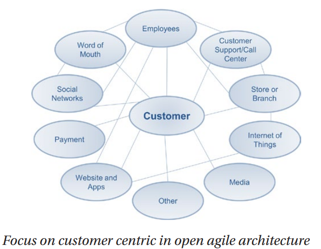
5) Open Agile Architecture (O-AA)


Requirements to become an agile enterprise:

- Get rid of silos and aim for interdisciplinary collaboration, focused on the best outcome for the customer.

- To become agile, teams must be empowered to take decisions for themselves. Therefore, teams must be skilled to spot opportunities and quickly identify and classify risks.


Change management is something different than feature management. 
New features come from requirements. Architect should validate 
1) Impact of requirements in terms of the overall business strategy. 
2) Does feature adding value? 
3) What is the impact of developing new features? 
4) What resources are required, what are the costs, and what is the value driver? 


Change control aspects:
• Scope
• Time
• Resources
• Risks
• Stakeholder views/ resistance
• Costs
• Quality


Monday, May 1, 2023

Build Web Portals

 Common Web Portal Architecture Diagram


On Premises vs Cloud Computing


How to use Azure APP Service?

Azure APP Service supports .net, java, go, python, node js, Ruby, and PHP


Azure Database Service


Azure storage account


Azure Storage Account types

- Blob Storage: Save all kind of file

- File Storage: the same as Blob Storage but support SMB protocol to allow attach it for Read/Write on a containers

- Table Storage: No SQL data store

- Queue Storage: Async Message


Storage Account Endpoints

https://<storageAccountName>.blob.core.windows.net

https://<storageAccountName>.file.core.windows.net

https://<storageAccountName>.table.core.windows.net

https://<storageAccountName>.queue.core.windows.net


Type of Blobs

Block Blob: store text and binary, max size 4.75TB

Page Blob: Random read and write operation, max size 8TB, support attach to azure VM

Append Blob: optimized for append, Only appended blocks, max size 195 GB


Blobs Access Tiers

Hot Storage Tier: when data is accessed frequently, storage cost: high, access cost: low

Cold Storage Tier: for infrequent access, storage cost: low, Access cost: high

Archive Storage Tier: for rare access, storage cost: lowest, access cost: highest 


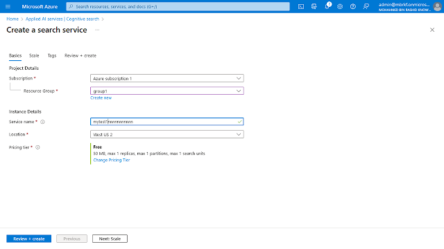
Azure Cognitive Search

Support FTS from data sources like SQL Server, Cosmos DB, Blob Storage, Table Storage….

Cognitive Search create searchable information out of unstructured contents by attaching AI to indexing pipeline.

Use case:

extract all articles that speak about UAE form all printed newspapers around the world.

We can provide you, scanned newspapers’ images. 

The main problem, that you do not know Chinese, Japanese, Turkish… 


Design Microservices Architecture with Patterns & Principles

monolithic ---> Layered - SOA ---> Microservices  ---> Event-Driven Architecture


use https://app.diagrams.net/ to create the system architect chart